Mainsprings

mainsprings: 

The mainspring is the heart of the timekeeping of any spring drive clock. If the mainspring is not oiled properly the clock will not work. The oil that is used is absolutely critical ; it must be able to work in a slow moving environment and it must be able to resist evaporation for many years. It is also very important that the oil be absolutely non corrosive. In my opinion the mainspring grease that is available through the various suppliers is probably the best to use. Listen to the mainspring unwinding as the strike runs if you hear the mainspring clunking or making a snapping noise : then the lubricant probably isn’t working. If this situation exists in the time mainspring then the clock will not keep time and may not even run at all. Mainsprings in the older clocks that have been around for many years have a buildup of hardened oil that is not removed by the ultrasonic process. This must be removed, or the clock will not work.The mainspring will stick erratically and cause timekeeping problems, and may actually bind up and release suddenly and cause a tooth on the spring barrel to be bent or even bend a tooth on the second wheel. If this happens when no one is there to hear the spring snap, then you will be befuddled when the thing just stops working after a careful overhaul.I have used 0000 steel wool on mainsprings; have also tried very fine emery paper #1000 or crocus cloth. The problem with using emery paper is that extreme care must be taken to remove all of the residue from the cleaning with the emery paper or the mainspring will be worse that it was before it was cleaned.After the mainspring has been cleaned and polished, if you ,a clean soft light colored cloth can be used to remove the residue; then run the spring through the ultrasonic cleaner. 

Posted in Clock repair | Comments Off on Mainsprings

Waterbury triple plate westminster chime

Clock Repair Archive – –    : 

Waterbury made a triple plate self correcting lantern pinion mechanism with time and strike style shutoff wires. On the left side back plate looking at the unit from the front , the lever on top of the trip lever is the self correct lever. Stamped on the back of the movement: Patented 5/24/1910 ; 1/23/1917 ; 1/29//1918 ; 5/21/1918 ; 5/27/1919 6/5/1924 ; 4/14/1925. The best way to approach this mechanism, if an overhaul is planned , is to treat it as two separate mechanisms with a common middle plate. As far as bushings are concerned , this is the least confusing, in my opinion, unless you are fortunate enough to work in an environment where it is possible to work uninterrupted. I prefer to do the chime mechanism first, because it is often necessary to rebush the gear system that winds the mainspring. Those gears are hard steel so be careful. they are usually somewhat loose on the shaft, and that is not usually a problem, Just be sure the bushings are as tight as possible. Check the #2 wheel chime bushing on the long end of the shaft; it is very close to the movement post, and if it is worn too severely, it may be a problem to get a bushing to fit. Be sure to assemble the chime silent lever before the mechanism is completely assembled. The trip lever is the one with the flat blued steel arm that extends into the front mechanism (the front mechanism being the section that carries the centerpost and the hour tube hand end) . The self correct lever is directly above the trip lever. The lock pin for the self correct stop on the 4th wheel must go past the self correct stop on all but the hour; so that when it releases on the hour it will be clear of the lock pin when it starts the travel for the hour sequence. The short tab on the bottom of the self correct lever fits in the small hole in the middle plate. This mechanism has a rack and snail on the front plate. The gathering pallet has 2 pins. The chime is tripped by the chime trip cam in the front plate mechanism on the back of the centerpost. There is a high lift on this cam that is meant to trip the chiming mechanism at the hour on the self correct. Looking at the back plate from the back of the clock the self correcting lever is on the upper right hand corner. It has a 3 pronged tension washer to hold it in place when it is moved by the pin on the 3rd wheel. The triple plate design allows for the time gear train and the strike ear train to be positioned at the front and the chime at the back. The warning wheel (5th wheel)) in the chime gear train has almost one turn before the lock position; this allows for the self-correct to function properly. the pin on the 4th wheel is the self correct pin. It works with the self correct lever; the high lift moves the lever to clear this pin on the hour. the sequence cam is on the 3rd wheel. the 3rd wheel o has a pin on the front of the wheel to trip the strike and a pin on the back to set the self correct lever to grab the pin on the 4th wheel.All of the slots on the 3rd wheel are the same depth because the self correct is done with the levers, This mechanism has a through the dial regulator at the 12 o’clock position and a chime silent lever below that . the rack index arm will move: it is riveted on in the mechanisms i have seen. The setting of the index arm is critical because the shutoff arm that rides in the grooves must be adjusted so it will work in conjunction with the gathering pallet. It must shutoff with the last pin on the gathering pallet having just cleared the last tooth on the rack. The mainspring measurements are as follows:

Time mainspring:.018in. X .750in. X 96in.
Strike mainspring: .014in. X .874in. X 78in.
Chime mainspring: .0225in. X .874in. X 78in.

The pendulum length is 7 ¼ inches from the top of the suspension to the bottom of the pendulum. The center arbor winds to the right , the right arbor winds to the left . and the left arbor winds to the right. The suspension spring is .0035in. thick , and 1.6 inches long . The key size is somewhere between a 7 and an 8 , an 8 fits loosely and a 7 fits very tightly. The regulator end is between a 3 and a 5 ; the 5 will work but it is quite snug.

Posted in Clock repair | Comments Off on Waterbury triple plate westminster chime

Warning pin position

Clock Repair Archive – –    

The warning pin position determines how much spin the strike or chime gear train has before the hammer load or any load is applied to it. This as absolutely critical on some mechanisms and on others; not so critical. Generally speaking , if there is trouble with the chime or strike binding it may very well be that there is not enough gear travel before the load is applied.

Critical on these:

  • Seth thomas 124
  • seth Thomas 113
  • chelsea ship’s bell clocks
  • All french clocks
  • Most Gustave Bekker clocks
  • Hubert Herr cuckoos
  • Regula cuckoos
  • Most older Junghans clock mechanisms

Not so critical on these:

  • One day german count wheel cuckoos
  • Quail cuckoos
Posted in Clock repair | Comments Off on Warning pin position

Clock repair tools

Clock Repair Archive – –     Tools: 

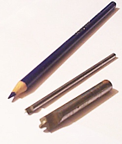
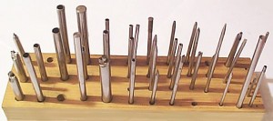
Be prepared to make your own tools or to modify commercially made items. Most of the tools that I have made have been made out of water hardening drill rod . punches: It is possible to buy commercially made punches in sets , but they will most likely not have all the combinations you need. It is not my intention to downplay commercially made tools ; and if you can afford them you will save a lot of time. Also , they can be altered if the need be. These are just some of the tools I have made and used:
more_tools
countersink: There is a countersink that you will need ; actually you will probably need a set of them.
Many times it will be necessary to cut the protruding edge of a bushing flush with the plate surface to clear levers or gears that ride close to the plate. The countersink with the wooden holder is one that I use to actually put a “bevel” if you will, on the inside of bushings after they have been pressed into the plate and drilled to fit the size of the pivot. The reason for this is that after drilling or reaming, or what ever you do to get the pivot to fit in the bushing; there will be a slight edge on the inside of the hole. This , believe it or not , is enough to stop a clock ; particularly if the bushing is several gears up from the power. Putting the bevel inside the bushing keeps edges of the metal from interfering with the smooth motion of the gear. This is typical of the characteristics of slow moving low torque gear train action in clocks. The way things function in that type of environment are not the same as a fast moving gear train. This theory is covered later in this journal. I use this countersink by hand. Also , on the outside of the bushing (the part of the bushing facing away from between theand two brass plates of the mechanism that contain the gears) a bevel will add to the ability of the bushing to hold oil as it is not desirable to have oil run down the outside of the plates leaving the bushing effectively almost “dry”. You want a very slight bevel in the inside which is why you will probably want to use this tool by hand. The other “countersink” actually is for reducing the thickness of a bushing after it is installed , without disturbing the flat surface. Not all bushings fit the thickness of all plates , and sometimes it is absolutely necessary to reduce the thickness of a bushing because of its position relative to other moving parts. If the inside of the two cutting edges are shaped just right this countersink will do the “beveling” while you do the job of cutting the thickness of the bushing down. I have made mine out of drill rod. They can be hardened by dipping them in water after you have heated them with a propane torch until they are dull red hot. Be extremely careful when you are using any kind of heat or torch. I cannot stress this enough. You may need to practice some with the tempering process. If you get the metal too hot it will become brittle and will break easily. When properly tempered these tools will cut brass or bronze. I haven’t tried cutting steel on a regular basis. I use emery paper with a solid backing to sharpen them.
These are available from various tool manufacturers; but you will probably have to make your own to custom fit to the bushing sizes. Many times it will be necessary to cut the protruding edge of a bushing flush with the plate surface to clear levers or gears that ride close to the plate. The countersink with the wooden holder is one that I use to actually put a “bevel” if you will, on the inside of bushings after they have been pressed into the plate and drilled to fit the size of the pivot. The reason for this is that after drillinandg or reaming, or what ever you do to get the pivot to fit in the bushing; there will be a slight edge on the inside of the hole. This , believe it or not , is enough to stop a clock ; particularly if the bushing is several gears up from the power. Putting the bevel inside the bushing keeps edges of the metal from interfering with the smooth motion of the gear. This is typical of the characteristics of slow moving low torque gear train action in clocks. The way things function in that type of environment are not the same as a fast moving gear train. This theory is covered later in this journal. I use this countersink by hand. Also , on the outside of the bushing (the part of the bushing facing away from between the two brass plates of the mechanism that contain the gears) a bevel will add to the ability of the bushing to hold oil as it is not desirable to have oil run down the outside of the plates leaving the bushing effectively almost “dry”. You want a very slight bevel in the inside which is why you will probably want to use this tool by hand. The other “countersink” actually is for reducing the thickness of a bushing after it is installed , without disturbing the flat surface. Not all bushings fit the thickness of all plates , and sometimes it is absolutely necessary to reduce the thickness of a bushing because of its position relative to other moving parts. If the inside of the two cutting edges are shaped just right this countersink will do the “beveling” while you do the job of cutting the thickness of the bushing down. I have made mine out of drill rod. They can be hardened by dipping them in water after you have heated them with a propane torch until they are dull red hot. Be extremely careful when you are using any kind of heat or torch. I cannot stress this enough. You may need to practice some with the tempering process. If you get the metal too hot it will become brittle and will break easily. When properly tempered these tools will cut brass or bronze. I haven’t tried cutting steel on a regular basis. I use emery andpaper with a solid backing to sharpen them.
Aluminum and brass blocks:
A couple of blocks of aluminum and brass about 3\4 inch square and 2 inches long will be quite useful. A small wooden mallet is very useful for installing cams , and friction fit sleeves made of brass. Make sure the wood is something hard like oak small brass headed hammer is also useful for working with punches to avoid flattening the ends of them as a steel hammer will do. Escape wheel teeth can be straightened by forming a piece of brass or soft steel rod to the shape of the space between teeth (providing there are at least 3 good teeth on the wheel; then work your way around the wheel pressing the piece between the teeth that are bent and after 2 or 3 times around the teeth will be quite uniform in distance from each other. Each time a pattern is made by all means mark it and save it because you will undoubtedly need it again.
Posted in Clock repair | Comments Off on Clock repair tools

Telechron electric clocks: 

Clock Repair Archive – – 

This is a type of electric clock that, in most cases, works on 110 volt 60 cycle electric current. There are quite a number of different types of Telechron electric clocks but only a few will be discussed in depth here. The 2 most common problems with the telechrons are the rotors (including the coil) and the actual mechanical part of the clock. It has been my experience that if the coil is bad, it is usually because of a power surge, improper handling, or just plain age.

Rotors that have a flat side on the shaft, but no replacement listed, can often be replaced by those with no flat side if the rpm rating, the size, the direction of rotation ( ccw for counter clock wise and c for clockwise ), and the diameter of the shaft are the same. If the only difference is the flat side on the shaft then either rotor will work. Of course you must file a flat side if all you can get is one with a round shaft. Always check the power cord; if it is worn anywhere replace it. Be very careful where the cord enters the coil it will break very easily. When the sequence is set(generally done after you have finished the bushing replacement and check the pivots for fit)as you reassemble the mechanism, be sure that the trip pins on the centerpost are at the hour position. The hour position is where the minute hand is exacty at the 12 and the mechanism is ready to strike the hour this will be determined by where the rest of the gear train is set with respect to the hammer lift assembly. If this is not done, the chime and strike will not release at the correct time and the gear train will bind up or the tempo of the chime-vs-strike will not sound pleasant. The hour strike will start too soon after the last note of the chime.

It is normal for the coil to heat up slightly however, it should not get too hot to touch, if it does, something is wrong. More than likely the coil is shorted. This can be a fire hazard so be careful and be sure to check coils out carefully. Some alternating current hum is normal however it shouldn’t be too noticeable. Sometimes the rotors are noisy; it is gear noise that causes this. Don’t confuse this with hum. Sometimes there will be both hum and gear noise. As of 1997, replacement rotors were available from most clock repair supply houses however, these rotors are becoming much harder to find. As of the writing of this journal some of them are no longer available. The serial number will usually be the letter M followed by four numbers. The rpm will usually be stamped on the outside of the case along with the serial number. Most rotors are designed to run on 60 cycle alternating current. There were some for 50 cycle current. There were coils made for 220/240 volt operation ( stove clocks ), but most are 110 volt. There were some coils made for 24 volt operation and some for 480 volt operation so be certain you know what coil you are dealing with before you apply power to it. If you use a 50 cycle rotor on 60 cycle power the clock won’t keep time, so be certain of the power frequency specification of the coil you are working on. If you have 50 cycle power, and change the 60 cycle rotor to a 50 cycle rotor, you must change the coil also; if you do not, the 60 cycle coil will heat up because it does not have enough inductance for the 50 cycle power and too much current will flow through it.

The old rotors were made of copper and were soldered together. They can be taken apart and repaired. Inside the capsule is a tiny ac induction motor that powers a reduction gear train. They are oil filled so I would not recommend opening them using any kind of heat. I have cut them open by chucking them up in a lathe and CAREFULLY cutting a groove in the top part of the capsule. If you look closely you can see where they have been soldered at the factory. The newer rotors can be cut open also. They are made mostly of aluminum. The gears inside the new rotors are plastic and so are some of the bushings. If you are very careful you can repair these rotors. The old rotors made of copper will usually have bronze bushings. These often wear and can be replaced. The gears also often wear. If these are worn the repair may not be as easy. Unless you have lots of time , and are very quick I would not recommend repairing these rotors as a general practice. As time goes on you may have no choice because as each year passes by fewer and fewer of them are available. They will usually have the rpm and direction of rotation stamped on the outside of the capsule.

Telechron electrics that don’t have keyholes for setting the strike and chime sequence can be set up by lining up the indentations on the back with the holes in the hammer lift cam instead of using the key pins. You are doing essentially the same thing as putting the pins through the “indexing” holes. The difference is that it might take several tries before you get the shutoff exactly correct. What I mean by keyholes and “indexing” holes is small holes that a (steel) pin will fit through. These are usually designed to accept pins .040 thousandths of an inch diameter). The idea is that you set the hour trip with the setscrew on the drive gear loose, then insert the pins which go all the way through the plate that holds the chime hammer lift assembly ;then through holes in the assembly itself. This holds the lift assembly in the correct position. The pins go in both sides , by the way. Once you have the pins in place and the hour trip cam set on the centerpost , you tighten the setscrew on the drive gear and the clock will be in sequence.

There have been Telechron clocks made with rack and snail type of design for the strike. The main thing to keep in mind is that this style must have no load on the hammers when the strike shuts off , or they will continue to strike sometimes and sometimes not. The shutoff lever for the strike hits the long pin and pops the strike drive gear away from the main rotor / time gear (which gives it its power). That pin must not be loose. If it is even slightly loose (and they do get loose) the clock will not work correctly all the time. The strike shutoff cam hammers must just have dropped when the cam is in the shutoff position. If this is not set within ten thousandths of an inch the clock will not work correctly all the time.

The hammer pads on these clocks tend to become quite hard and make the clock sound “tinny”. If you are repairing clocks for a living , DO NOT change these unless the customer specifically asks you to. If you change them you will change the sound of the clock and you will no doubt have a very angry customer in your store when they listen to their clock for the first time after you have repaired it and discover that you have changed their family heirloom. Trust me on this once you replace those old pads the clock will NEVER sound the same again and you will not be able to get the old sound back. You will be up to your backside in alligators and the swamp won’t even matter any more!

If you own one of these and want to change it consider that the originals on the older telechrons were leather. It tends to harden up over the years. I would suggest using a plastic end such as the ones used in the modern European clocks. They can be made to fit and can be ordered from suppliers. And , yes , you are changing the clock. Keep that in mind before you decide to change it. I’m not recommending you change the clock, I am saying if you must change it to sound softer use plastic. However , it may not be much of a change. If you want it original , just be happy with a tinny sound. I cannot in good conscience recommend using leather replacements

Posted in Clock repair | Comments Off on Telechron electric clocks: 

Count wheel issues

(Thanks to Phil for his question that helped to formulate this part)

COUNT WHEEL PROBLEMS AND SOLUTIONS:
Cuckoo clocks have their own special set of situations. Many cuckoo clocks of the count wheel variety use only gravity (as opposed to spring activated return) to bring the levers back down after the centerpost cam or wire trips the strike gear train into the lock and then release routine. Because of this, the play in the bushings that the trip levers ride in must be as friction free as possible with as little play as possible – yet still allowing the lever to be free to move. All of the angles on the working faces of these levers are critical. The shut off lever must grab the pin on the warning wheel (5th wheel) with about the thickness of the pin to spare – usually, depending on the amount of weight used to run the particular clock you are working on. The count wheel must not be loose on its bushing mount, if it moves (wobbles) slightly then there could be shutoff problems. The weights must be appropriate for the mechanism and many of these older clocks have had the weights replaced so long ago that it may not be possible to know if they are the original or not. Have a test rack to set the mechanism up on outside of the case. Watch the levers carefully as they operate. If they pop up slightly when the strike is tripped into the “lock” position the angle is wrong or the working face of the lever where it meets the pin in the 5th wheel (warning wheel) is defective. The pin in the warning wheel may be slightly loose. Watch the trip and shutoff levers while the mechanism operates they should not move around “much”. The “much” is the caveat because it takes a lot of experience to know just how much wiggle in a shut-off lever is too much.

Consider the play in the center post, the warning wheel bushings, the trip lever and the lift levers’ bushings, and the count wheel bushing: 2 thousandths of an inch off on each makes 5X2 or 10 thousandths of an inch – enough to cause problems, and the position of each may come together in the additive mode irratically causing problems in a very chaotic way, or there may be a pattern to the additive errors every 360 degrees or 180 degrees since we are deaing with circular motion. Getting the feel for how a mechanism should act is the key to success. After watching enough of them you will have enough of an idea of how they should look that it will get easier to find the problems.

Now spring drive mantle clocks of the T&S count wheel variety… Most of these (but not all) will have return springs on the shutoff lever. Often these springs are fatiqued or have been replaced with material of incorrect strength. This is a weak point on this type of mechanism. The end of the shutoff lever that fits into the slots on the count wheel can get a groove worn in it over many years of operation. This little square groove in the lever will move back and forth as the shutoff lever’s endshake allows; thus causing the strike to shut off irratically. The same groove can get worn in the trip lever on the center post which will also be irratic depending on endshake modulated position. On old (1800’s) T&S clocks the shutoff levers’ pivots are often worn – this will cause the strike to be irratic. These pivots must be smooth and true (the same is true for cuckoo clocks). They will need to be replaced or reshaped and polished. This can be very difficult because to chuck them up in a lathe and spin them is downright dangerous. If you have wire chucks it is possible to do this but it must be done, as you can imagine, very very carefully and it takes a long time to accomplish this task. Since the angles on these levers are absolutely critical I do not recommend trying to make a new shutoff lever unless you have lots of experience setting them up. If you can devise a way to accrurately measure all of the angles before you disassemble them that might be a viable solution. 

Posted in Clock repair | Comments Off on Count wheel issues

WHAT ABOUT SOLDERING IN THE REPAIR OF CLOCKS?

If you don’t absolutely have to DO NOT SOLDER ANYTHING ON A CLOCK. I say this because I have seen thousands of clocks with blobs of solder and acid flux all over them, many of them destroyed because of it. For example, simply tack soldering gear teeth on a gear to fix the gear is something one should never do. This is an insult to the owner, the maker, and the repair persona. What usually happens is it holds long enough for the owner to wind it up a few times then it lets go and destroys more that just the gear. Or worse yet, it may hold for several years, and then let go. This opinion is because of many bad experiences with clocks other persons have ruined. It is very discouraging to open up a pristine looking french clock, only to find it has been butchered with a punch and blobs of solder. Because of this, it is important to realize, that other repair persons may not be as negative about solder as I am; and it is true that it could have been repaired during the war when no brass was available for repairs, however, a good repair person can tell just by looking whether a clock has been repaired recently or not. How, you might ask? You look at the oil ( or lack of it ) on the verge, you look at wear spots with an eye loop, you look at the condition of the pivot ends, you look at the lustre of the entire mechanism, you look at the inside of the cabinet, you look for traces of dust, you listen very carefully to the mainsprings and pay close attention to their feel as you let them down. When you have done this many times on many clocks, you will be able to tell if a clock has been worked on recently or not; then you will know the reason why there may have been soldering where there was not an immediate necessity.

If you must solder a part on a clock, silver solder is ok but be careful because heating brass makes it very soft. You can ruin a gear or a barrell if you are not careful. If you see the brass get red hot, you have already ruined it. Right before the brass gets red hot you have already ruined it. Electronic solder will not work. It is not strong enough. There is solder available that requires only slightly more heat than a soldering iron, and is much sronger. It is available from most clock repair parts suppliers. It is possible to solder parts with this solder without ruining them, but you still must be very careful. Do not overheat the brass. Try a heating a piece of scrap brass and then hammering it and working with it before you ever try any soldering on a clock. This is the best way to learn for yourself how brass reacts to heat. Do keep in mind, however, that the size and shape of a piece of brass will affect how it reacts to heat.

Soldering in itself is somewhat of an art. If you have worked in electronics or plumbing and understand how solder works, then you have a head start, but you are not there yet. Brass does not react the same way as copper, or tinned copper wire, it is not as forgiving. Don’t even attempt any kind of soldering on clocks until you fully understand the basics of it first.

Posted in Clock repair | Comments Off on WHAT ABOUT SOLDERING IN THE REPAIR OF CLOCKS?

How to fix problems with the chimes

HOW DO I FIX THE CHIMES?

Now a little bit about chime adjustment. I have had numerous requests about this topic. First lets get on the same page, so to speak, about the meaning of chime, and stike, and gong. For our purposes here the chime will mean the melody that plays on the quarter hours. The strike will mean the hour count. Gong will mean what ever is the sound making device. Things such as bells, wires, rods, steel rods, or steel coils are included. If there is an issue with a specific type of gong material it will be indicated. Hammer will mean the device that hits the gong. It usually looks like a miniture hammer.

There are several aspects to chime and strike. One is volume. Another is tempo. A third is the actual pitch of the notes and whether or not the chord on the hour strike is “in tune” and whether or not the melody sounds in tune.

Volume can mean different things to different people. Here we are talking about amplitude, not frequency. A higher pitch may sound louder to some people, depending on their hearing, so if you are in business, be aware of this. As you might guess the amplitude or volume is pretty much directly related to how hard the hammer hits the gong. Consider a hammer that is solid brass (or steel) hitting a gong; the frequency spectrum of sound produced will be on the high end making a “tinny” sound. You can change the volume of this by reducing the impact of the hammer hitting the gong. To do this change the return spring to one with less strength, move the hammer away from the gong so it hits with less force, or reduce the distance the hammer travels ( reduce the throw ) before it hits the gong. The last two methods are the best choices. The first method is a last resort and one must be very careful when altering a clock’s design. So reducing the throw or moving the hammer away from the gong are the best methods for changing volume. DO NOT BEND THE GONG, EVER. A good general rule ( when making an adjustment in clock repair ) is that if you saw it move it moved too much. Adjusting hammers that produce sound for the chime or strike is very difficult unless you have lots of experience. The above gives you one perspective.

SOME FACTS ABOUT THE SOUND OF CHIMES:

One: If you hit a gong hard it will produce a loud sound and will produce a different frequency spectrum of sound with more amplitude than if you hit it with less force.

Two: A hard substance on a hammer such as steel or brass will make a high pitched sound when it hits the gong, and will be percieved as loud to many people.

Three: A soft substance on a hammer such as cloth, or plastic, or rubber, will fail to produce high amplitude high frequency vibrations. This will be percieved as soft by many people.

Four: A longer gong rod, or larger bell does not necessarily produce a lower pitch than does a slightly shorter rod or smaller bell.

Five: The more substance ( mass ) a given gong material has the lower the frequency produced when it is hit by the hammer.

Six: The design of the gong where it attaches to the mounting screw will affect the frequency of vibration along with the size and length.

The tempo of the strike or chime is directly related to adjustment. This is a very complicated subject and is different for every clock. The tempo is determined by the actuating mechanisms that lift the hammers. These usually consist of pins, or cams, or star wheels, or drums with lift pins in specific areas attached to gears.

There is also the issue of sequence. Most modern clocks are self correcting. For example, the “Westminister” chime has a melody that plays four notes on the quarter hour, eight notes on the half hour, twelve notes on the three quarter hour, and sixteen notes on the hour followed by the hour count. These mechanisms are set up so as to self correct if they get out of sequence. If one of these clocks is allowed to run down and stop, the sequence will probably be off for at least one hour. If the hour count rack is stuck behind the snail, it may take up to 12 hours to correct itself. If, when the clock stops, the owner forces the minute hand ahead, in an attempt to reset it, there will usually be damage to the trip lever inside and the clock will not work right until the correct angle is restored to this lever. If the owner moves the hour hand to make it match the count, the clock will be off permanently and they will not even realize what they have done. If they are lucky they will not break the hour hand when they try to move it.

WHAT IF THE CLOCK DOES NOT CHIME ( OR STRIKE ) EXACTLY WHEN THE MINUTE HAND REACHES THE 12, 3, 6, OR 9? ( 12 OR 6 IN THE CASE OF A TIME AND STRIKE CLOCK )

This can be caused by a number of different problems. The most common cause of this is that the minute hand gets forced ahead after the clock runs down and stops; or the minute hand gets moved while the clock is chiming or striking. Most of the time the owner won’t realize the damage they have done. This is not the only aspect of this problem by any means. If the trip cam is loose, or if the trip lever is loose or bent at the incorrect angle the same problem may occur. If the trip cam is worn or if the pin used as the working surface on the trip lever is loose; again the same problem may occur. If the minute hand hub slips slightly, the chime or strike won’t trip when the minute hand is at the corresponding 12, 3, 6, or 9. This problem can also be caused by too much oil on the trip lever, or trip lever axel or a broken or jammed return spring on the trip lever. This can be a very difficult problem to solve. This is where the repair person needs to have a lot of experience and a very sharp eye for things out of place in most every kind of mechanism. These are just some of the aspects of this problem.

Posted in Clock repair | Comments Off on How to fix problems with the chimes

Timekeeping issues

TIMEKEEPING ISSUES

A note about timekeeping with the stock pendulum that is designed to be used with a given clock: Shorten this pendulum and the clock will run faster. Lengthen this pendulum and the clock will run slower. In other words turn the adjusting nut to your left to make the pendulum longer so the clock will run slower. Turn the adjusting nut to the right to make the pendulum shorter so the clock will run faster. One full turn. (Make sure the pendulum actually moves when you do the adjusting; sometimes the part inside the pendulum bob is loose and slips when you try to make an adjustment.) Make note of the time. Check the clock in 2 days. Make the adjustment again of one full turn. Make note of th time Check the clock in 2 days. Keep this up until you have done two things: Acquired a record of how many turns it takes to make a specific change in timekeeping ; and have the clock keeping time. A useful formula for calculating timekeeping data is: L = Li*(1±E/R)². L is correct length, Li is incorrect length, E is error in hours, and R is length of test run in hours.

Now this interesting question. What do you compare the clock to ? You would be surprised what I have found customers comparing their clocks to for timekeeping adjustments. The TV (the TV is the best one I have heard), a digital clock,( a digital clock without a number for seconds will drive you nuts if you want to get more than plus or minus 1 minute accuracy), the clock on the town hall, my cuckoo clock, the computer clock, the clock in my car, the list goes on. My point here is be sure you are using an accurate comparison, and only ONE clock for comparison, or you will be spinning your wheels – – literally! The big mistake most people make is assuming that all clocks in the realm of TV, government, business, and technology, are somehow all set to exactly the same time, so they compare to a different clock every time they make an adjustment. If you are a clock repair technician, this is obvious to you, but to the average person it may not be so obvious.

Posted in Clock repair | Tagged | Comments Off on Timekeeping issues

Can a clock be “wound too tight”?

WHAT ABOUT THE SAYING THAT “THE CLOCK IS WOUND TOO TIGHT”?

You can only wind a spring drive clock so far and then either the spring will break, or the key will break, or one of the gears will be ripped loose. I have seen some clocks that have been forced so hard that the arbor actually has snapped. The old Urgos spring drive clocks have an arbor that has a small groove cut in it for assembly convvenience that will snap if you force it. If a clock needs repair and it is wound fully many times the mainspring will stick. This gives the appearance of the clock being wound too tight. Essentially , from the users perspective , it is. From the repairperson’s point of view it needs cleaning. Each coil of the mainspring has only a fraction of the power of the total power of the mainspring so if the surface tension of the mainspring grease is to the point where it does not allow the spring to release ( because oil / grease thickens up over time and becomes “sticky”) then when the mainspring is wound FULLY all the coils stick together and give the illusion that the mainspring or clock is broken. It sort of is, but not from over winding. If you overwind a clock and break it , believe me you will know. You may loose finger nails faster that you can see , there will be noise with a volume directly perportional to the size of the spring. 
On weight drive clocks, often the pulley/pulleys will catch on part of the mechanism or mechanism mounting hardware if the clock is fully wound and give the impression of the clock being wound too tight. Also, the cable can come off the pulley and get stuck between the pulley frame and the pulley this may prevent the associated gear train from functioning. These are things to look for.

Posted in Clock repair | Comments Off on Can a clock be “wound too tight”?